

Compact Antenna Test Range (CATR) Facility
Compact Antenna Test Range (CATR)
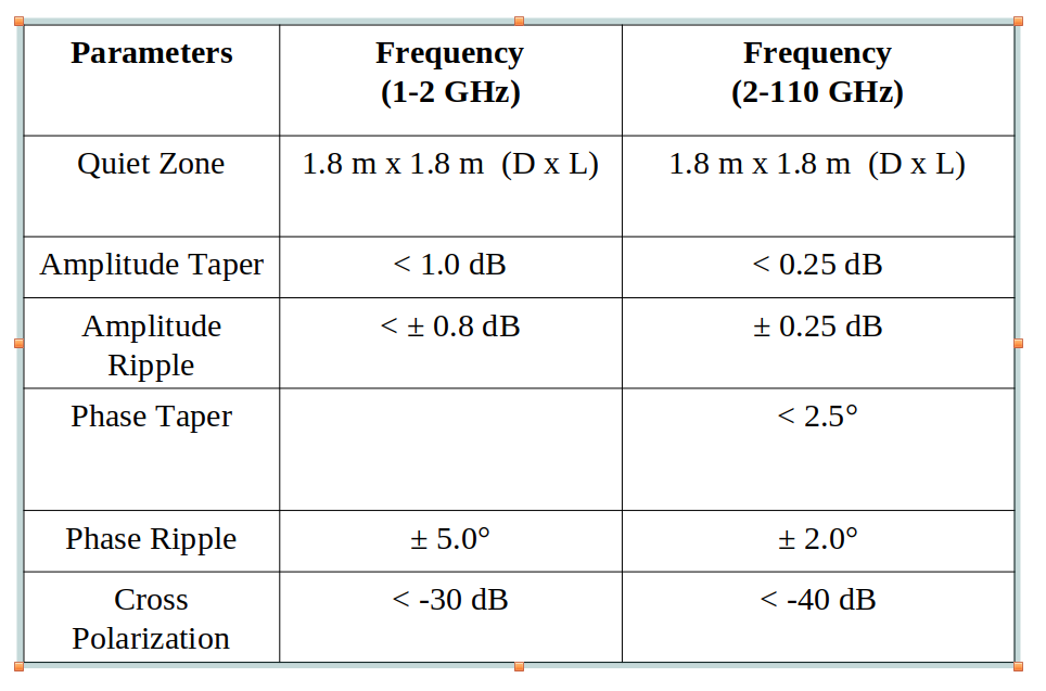
Compact antenna test range facility offers the best solution and allows characterization of antennas from lower microwave frequency range to higher millimeter wave frequency range, typically from 2-110 GHz within a compact space and under controlled environment at a reasonable cost.
Advantages of CATR Facility
Eliminates the need of very long test range
Generates plane wave front in a very short distance (typically 10-20 meters)
Requires lesser absorbers
Needs lesser transmitting power
Provides larger size quiet zone uniform over a very large frequency range
Compact Range
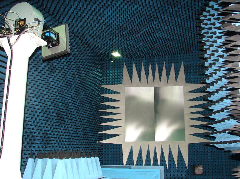
The principle of compact antenna test range is to collimate a spherical wave front in order to obtain a plane wave simulating far field conditions for antenna, Radome measurement, RCS studies and Millimeter wave system evaluation in a chamber of reduced length.
Measurement Capabilities
Antenna
Radiation pattern, Beam width, Side Lobe Level
Peak Gain and location, Bandwidth
Polarization (Linear & Circular)
Cross polarization discrimination
Precise identification of the bore sight axis
Null depth and location
Axial ratio
Phase plot
Multi Channel measurement
Radome
Transmission efficiency
Pattern distortion- Beam width
SLL increase
Peak /Null location shift
Lobe imbalance
Radar Cross Section (RCS)
RCS Vs down range/Cross range Vs Angle
RCS Vs. frequency Vs. Angle
The Compact Antenna Test Range facility basically consists of the following:
Range Reflector with feed arrangement
Performance Network Analyzer (PNA) act as a source and receiver.
Five axes positioner with control units.
Pattern recorder, data acquisition and analysis software MiDAS.
Standard Gain Horn Antenna.
RF microwave absorber for making the test chamber anechoic.
Shielded compact test range hall.
Optical Alignment System.
HVAC unit, Diesel Generator (50 KVA) and UPS 15 KVA.
 Electrical Specifications